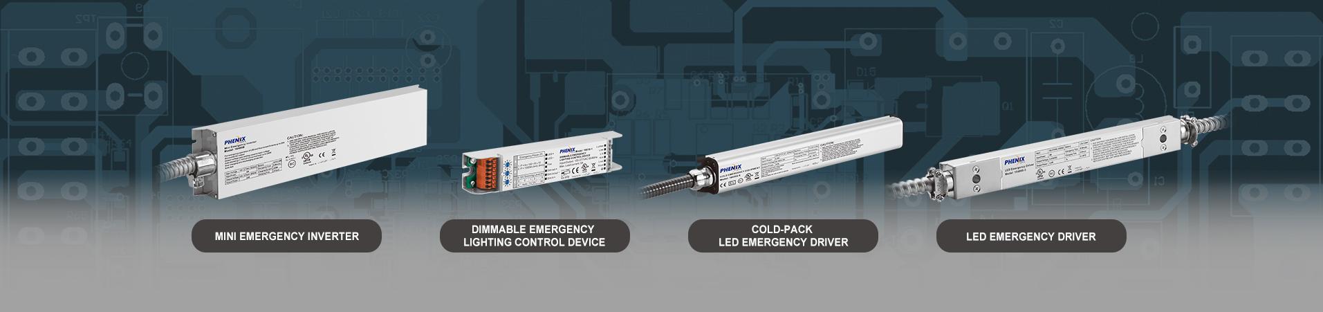
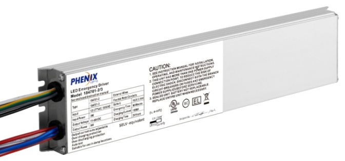
Class 2 Output Led Emergency Driver 18470X-X
Short Description:
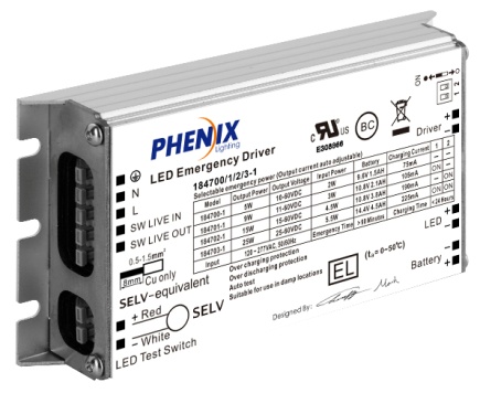
18470X-X Class 2 Output LED Emergency Driver, 5W, 9W, 15W, 25W.


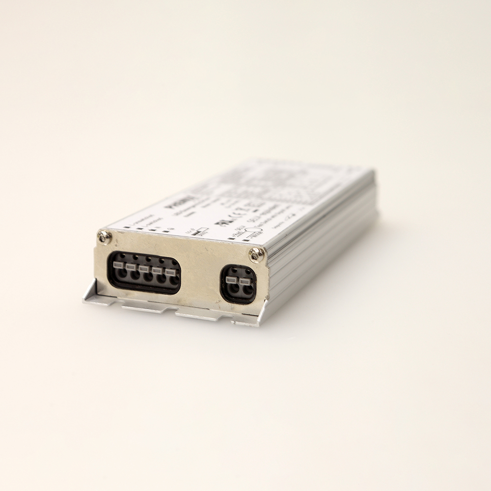
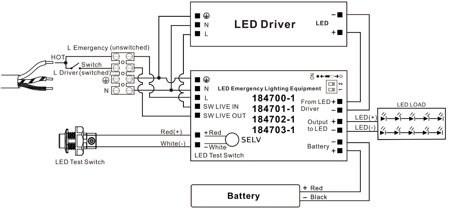
18470X-1
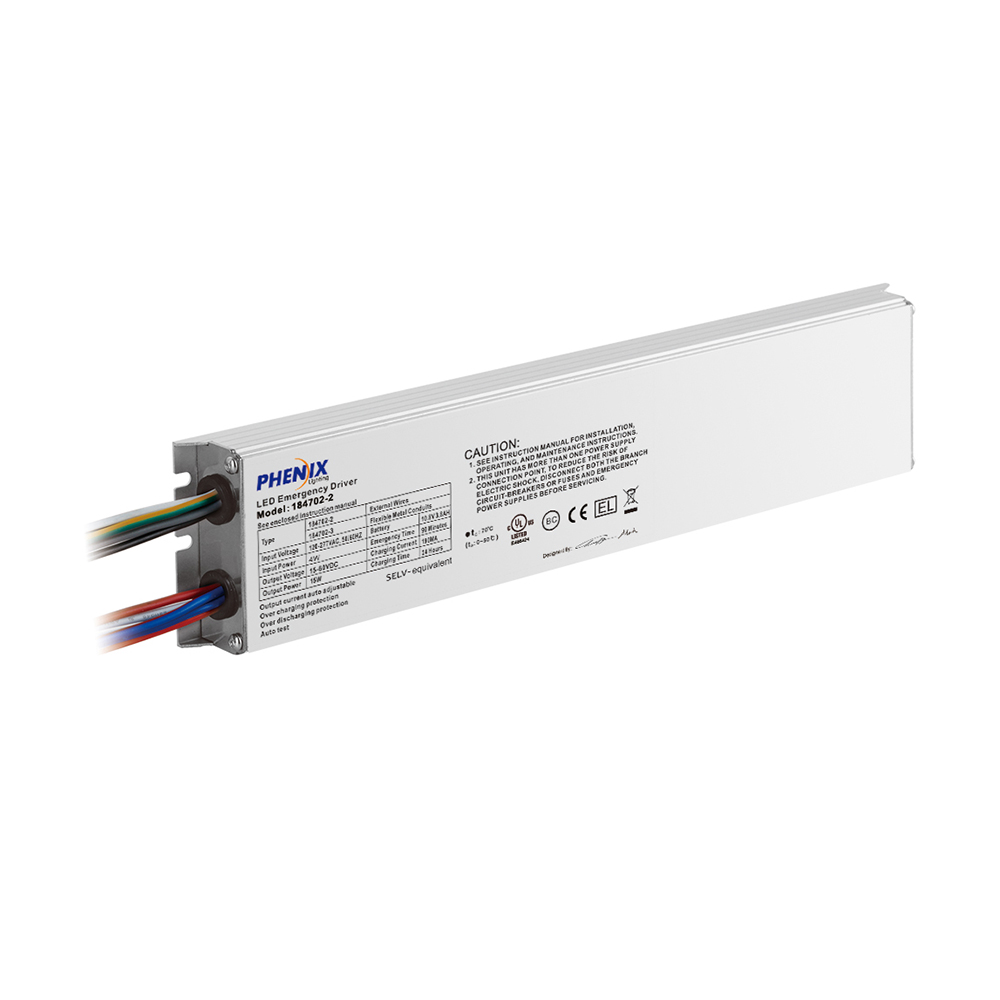
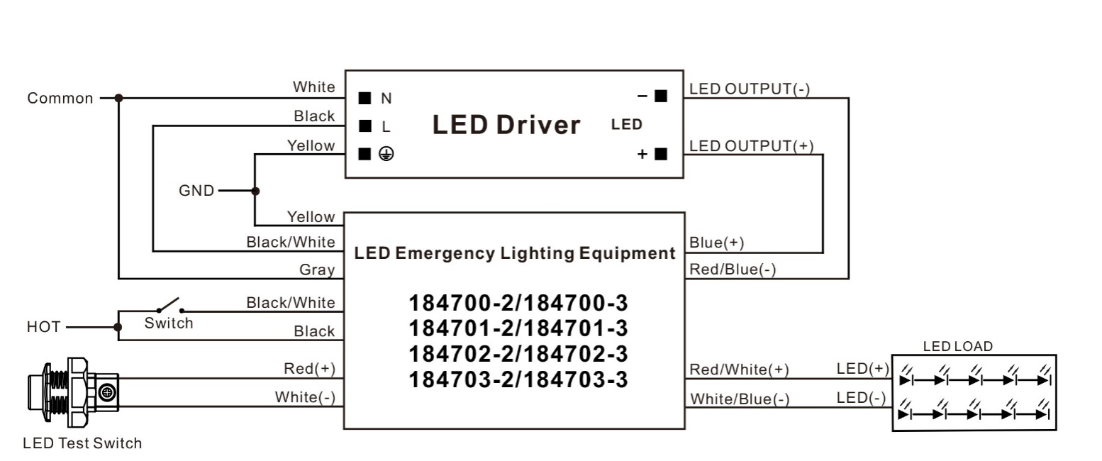
18470X-2
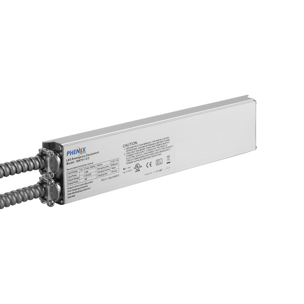
18470X-3
1. Emergency operation of LED luminaires, for both factory and field installation.
2. Perfectly compatible with most AC LED drivers.
3. Constant emergency power output: Class 2 output voltage (10-60V), output current auto adjustable.
4. Various emergency power options:
|
18470X |
Emergency power |
|
184700 |
5W |
|
184701 |
9W |
|
184702 |
15W |
|
184703 |
25W |
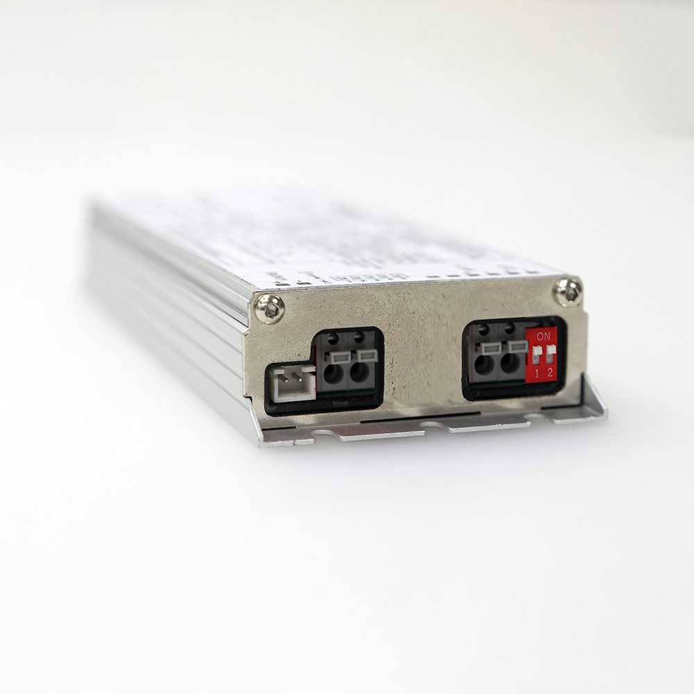
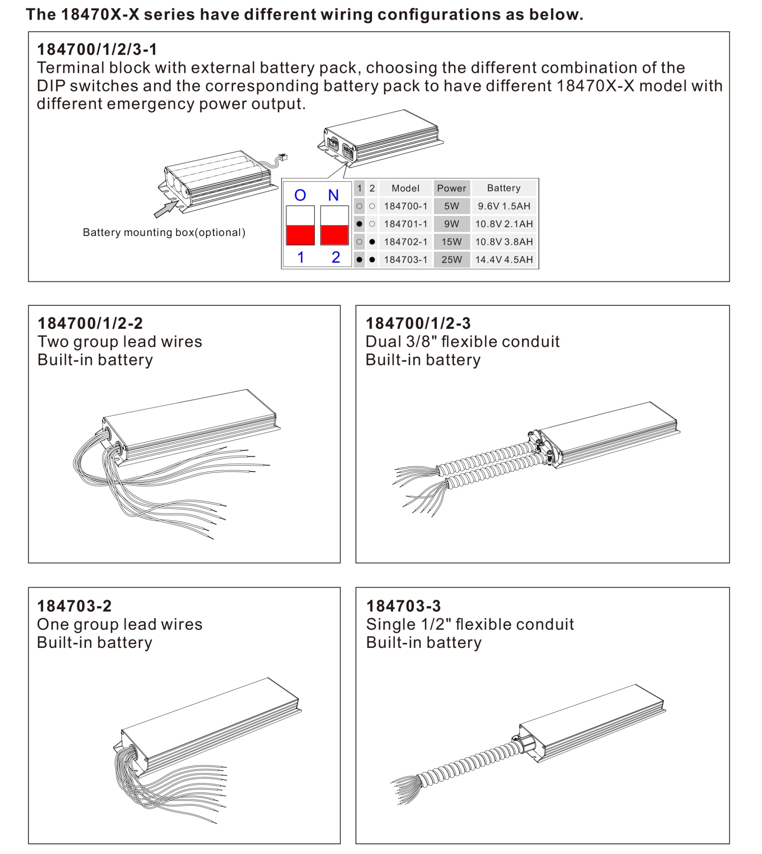
5. Various connection options:
|
Type |
Connection way | UL approval |
|
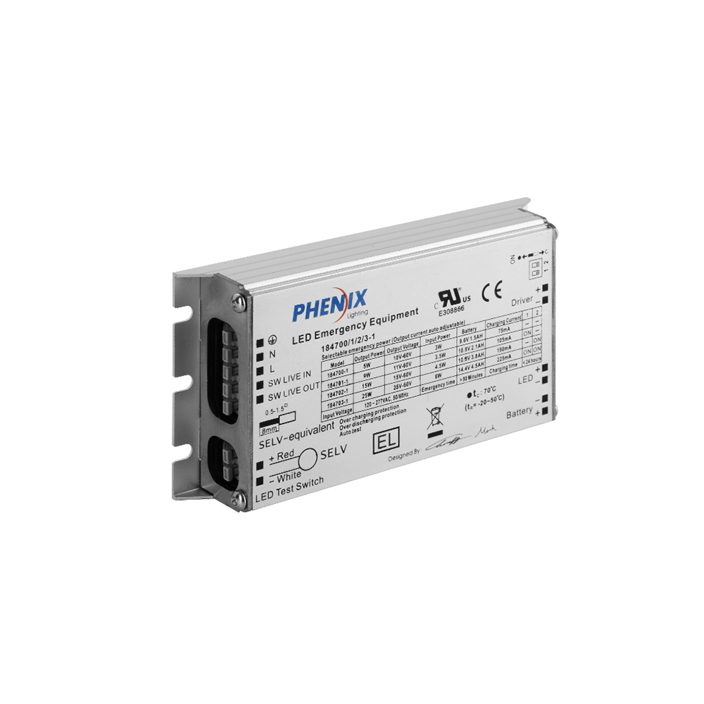
18470X-1 |
Terminal block, External Battery |
UL Recognized |
|
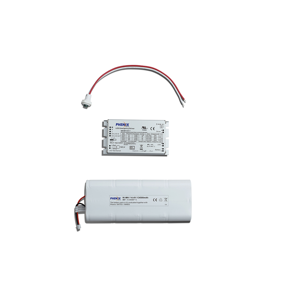
18470X-2 |
External wire, Built-in Battery |
UL Listed |
|
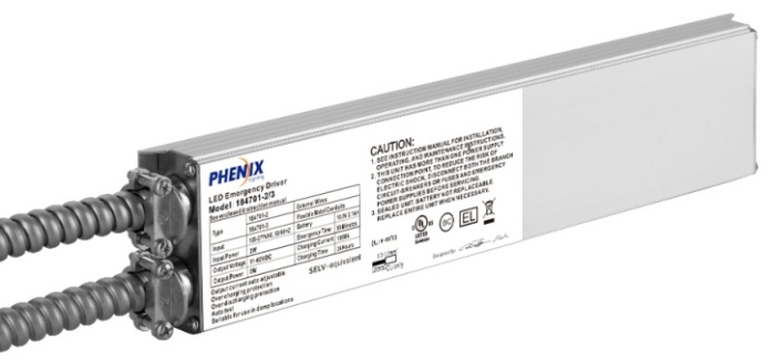
18470X-3 |
External wires with metal conduits, Built-in Battery |
UL Listed |
6. Auto Test
7. Slim aluminum housing
8. Suitable for indoor, dry and damp applications
| Type | 184700-X | 184701-X | 184702-X | 184703-X |
| Rated voltage | 120-277VAC 50/60Hz | |||
| Rated current | 0.04A | 0.05A | 0.07A | 0.1A |
| Rated power | 2W | 3W | 4.5W | 5.5W |
| Emergency output power | 5W | 9W | 15W | 25W |
| Output voltage | 10-60VDC | 11-60VDC | 15-60VDC | 25-60VDC |
| Output current | 1 A (Max.) | |||
| AC driver output current | 5 A (Max.) | |||
| Operation frequency | 320kHz≥f≥50kHz | |||
| Power factor | 0.5 | |||
| Battery | Ni-MH/Li-ion | |||
| Charging time | 24 Hours | |||
| Discharge time | >90 Minutes | |||
| Charging current | 0.08A | 0.11A | 0.19A | 0.23A |
| Life time | 5 years | |||
| Charging cycles | >500 | |||
| Operation temperature | 0-50℃ (32°F-122°F) | |||
| Efficiency | 80% | |||
| Abnormal protection | Over load, Inrush current limiting, over temperature, open circuit, short-circuit protection with auto-reset | |||
| Wire | 0.75-1.5mm2 | |||
| EMC/FCC/IC standard | EN55015, EN61547, EN61000-3-2, EN61000-3-3, FCC part 15, ICES-005 | |||
| Safety standard | EN61347-1, EN61347–2-7,UL924,CSA C.22.2 No. 141 | |||
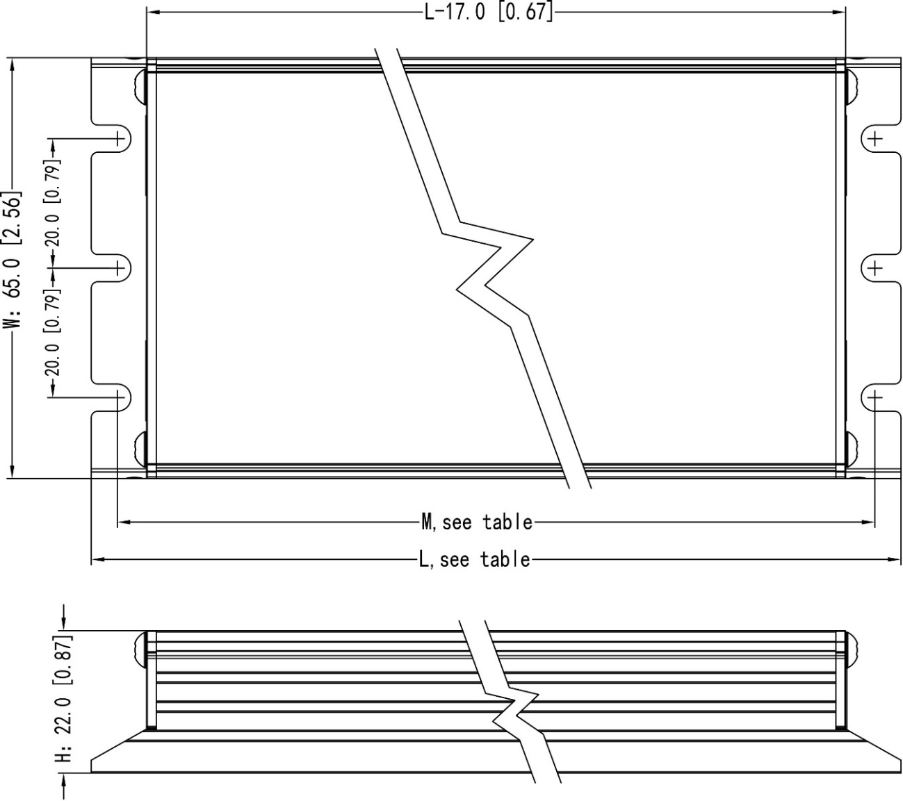
| Meas. Module 18470X-1 mm [inch] | L125 [4.92] x W65 [2.56] x H22 [0.87] Mounting Center: 117 [4.61] | |||
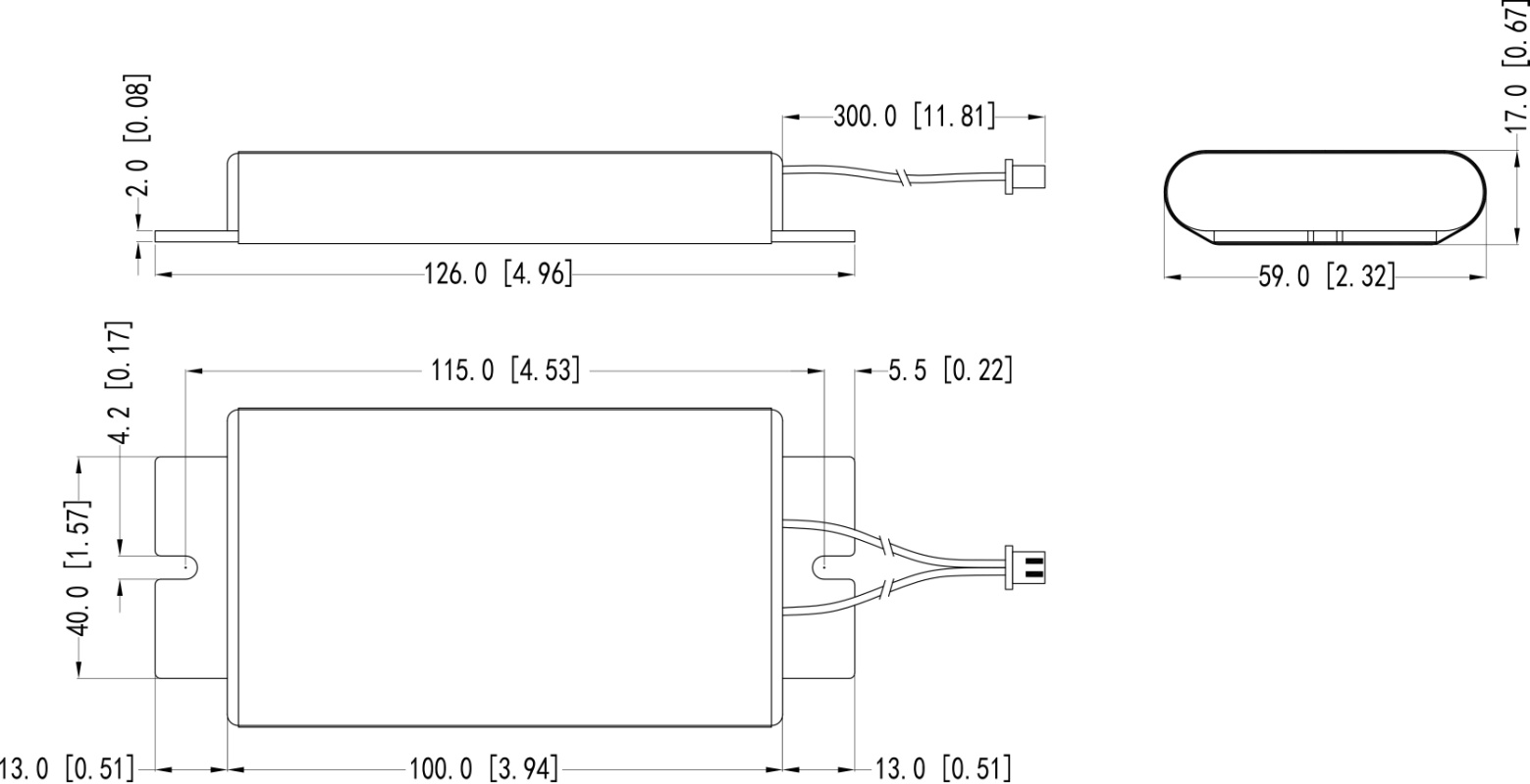
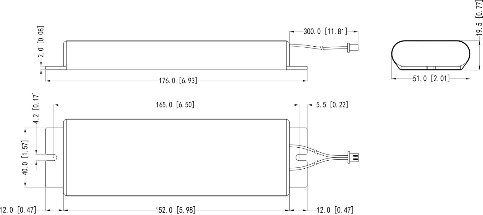
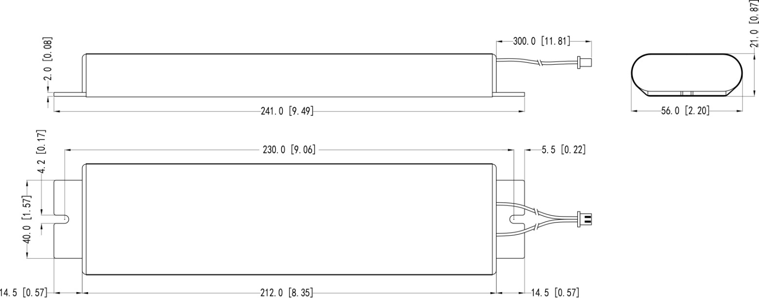
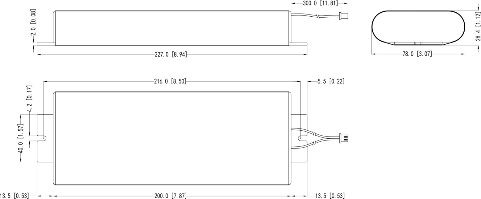
| Meas. Battery pack 18470X-1 mm [inch] |
9.6V 1.5Ah: L126 [4.96] x W59 [2.32] x H17 [0.67] Mounting center: 115 [4.53] 10.8V 2.1Ah: L176 [6.93] x W51 [2.01] x H19.5 [0.77] Mounting center: 165 [6.50] 10.8V 3.8Ah: L241 [9.49] x W56 [2.20] x H21 [0.83] Mounting center: 230 [9.06] 14.4V 4.5Ah: L227 [8.94] x W78 [3.07] x H28.4 [1.12] Mounting center: 216 [8.50] |
|||
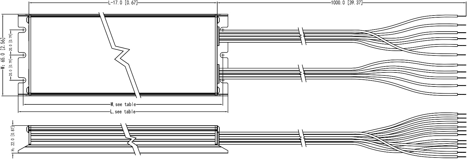
| Meas. 18470X-2mm [inch] |
184700-2: L260 [10.24] x W65 [2.56] x H22 [0.87] Mounting center: 252 [9.92] 184701-2: L307 [12.09] x W65 [2.56] x H22 [0.87] Mounting center: 299 [11.77] 184702-2: L372 [14.65] x W65 [2.56] x H22 [0.87] Mounting center: 364 [14.33] 184703-2: L358 [14.09] x W82 [3.23] x H30 [1.18] Mounting center: 351 [13.82] |
|||
| Meas. 18470X-3mm [inch] |
184700-3: L260 [10.24] x W65 [2.56] x H22 [0.87] Mounting center: 252 [9.92] 184701-3: L307 [12.09] x W65 [2.56] x H22 [0.87] Mounting center: 299 [11.77] 184702-3: L372 [14.65] x W65 [2.56] x H22 [0.87] Mounting center: 364 [14.33] 184703-3: L358 [14.09] x W82 [3.23] x H30 [1.18] Mounting center: 351 [13.82] |
|||
18470X-1 MODULE
|
Item No. |
L mm [inch] |
M mm [inch] |
W mm [inch] |
H mm [inch] |
|
184700-1 |
125 [4.92] |
117 [4.61] |
65 [2.56] |
22 [0.87] |
|
184701-1 |
125 [4.92] |
117 [4.61] |
65 [2.56] |
22 [0.87] |
|
184702-1 |
125 [4.92] |
117 [4.61] |
65 [2.56] |
22 [0.87] |
|
184703-1 |
125 [4.92] |
117 [4.61] |
65 [2.56] |
22 [0.87] |
Dimension unit: mm [inch]
Tolerance: ±1 [0.04]
BATTERY: Ni-MH AA/9.6V/1.5Ah for 184700-1
BATTERY: Ni-MH A/10.8V/2.1Ah for 184701-1
Dimension unit: mm [inch]
Tolerance: ±1 [0.04]
BATTERY: Ni-MH 18700/10.8V/3.8Ah for
184702-1
BATTERY: Ni-MH C/14.4V/4.5Ah for
184703-1
Dimension unit: mm [inch]
Tolerance: ±1 [0.04]
18470X-2
18470X-3
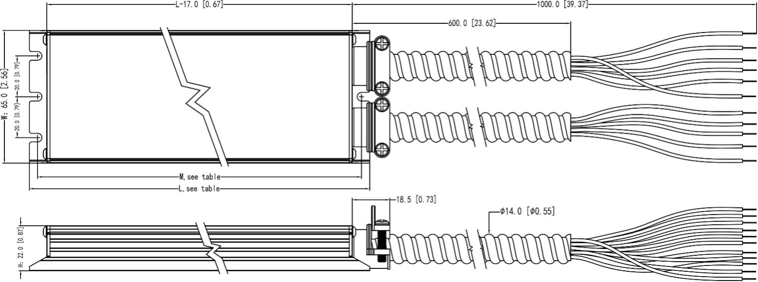
| Item No. | L mm [inch] | M mm [inch] | W mm [inch] | H mm [inch] |
| 184700-2/3 | 260 [10.24] | 252 [9.92] | 65 [2.56] | 22 [0.87] |
| 184701-2/3 | 307 [12.09] | 299 [11.77] | 65 [2.56] | 22 [0.87] |
| 184702-2/3 | 372 [14.65] | 364 [14.33] | 65 [2.56] | 22 [0.87] |
| 184703-2/3 * | 358 [14.09] | 351 [13.82] | 82 [3.23] | 30 [1.18] |
Only one entry for wires
Dimension unit: mm [inch]
Tolerance: ±1 [0.04]
18470X-1
18470X-2 or 18470X-3
Dimension unit: mm [inch]
Tolerance: ±1 [0.04]
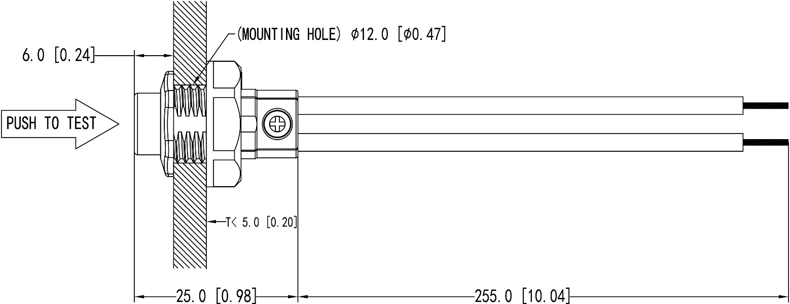
OPERATION
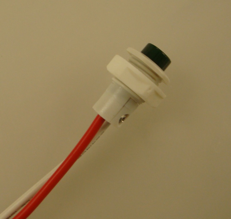
When AC power is applied, the LED test switch is illuminated, indicating that the batteries are being charged.
When AC power fails, the 18470X-X automatically switches to emergency power, operating the lighting load at rated emergency power. During power failure, the LED test switch will be off. When the AC power is restored, the emergency 18470X-X switches the system back to normal mode of operation and resumes battery charging. The minimum emergency operation time is 90 minutes. The charging time for a full discharge is 24 hours. A short term discharge test may be conducted after the 18470X-X has been charging for 1 hour. Charge for 24 hours before conducting a long term discharge test.
TESTING AND MAINTENANCE
The following Periodic testing is recommended to ensure the system is working correctly.
1. Visually inspect the LED test switch (LTS) monthly. It should be illuminated when AC power is applied.
2. Conduct a 30-second discharge test by switching off the emergency breaker every month. The LTS will be off.
3. Conduct a 90-minute discharge test once per year. The LTS will be off during test.
AUTO TEST
The 18470X-X has an Auto Test feature which saves cost by reducing the need for manual testing.
1. Initial Auto Test
When the system is connected properly and powered on, the 18470X-X will perform an initial Auto Test. If any abnormal conditions exist, the LTS will blink quickly. Once the abnormal condition is corrected, the LTS will function correctly.
2. Preprogrammed Scheduled Auto Test
a) The unit will conduct the first Monthly Auto Test after 24 hours and up to 7 days after initial power on. Then monthly tests will be performed every 30 days.
b) Annual Auto test will occur every 52 weeks after initial power on.
– Monthly Auto Test
The Monthly Auto Test shall be executed every 30 days, and will test;
Normal to emergency transfer function, emergency, charging and discharging conditions are normal.
Monthly test time is approximately 30 seconds.
– Annual Auto Test
Annual Auto Test will occur every 52 weeks after the initial 24 hours full charge, and will test;
Proper initial battery voltage, 90-minute emergency operation and acceptable battery voltage at the end of the full 90-minute test.
If the Auto Test is interrupted by a power failure, a full 90-minute Auto Test will occur again 24 hours after the power is restored. If the power failure causes the battery to fully discharge, the product will restart the Initial Auto Test and Preprogrammed Scheduled Auto Test.
MANUAL TEST
1. Press the LTS 1 time to force a one-second emergency test.
2. Press the LTS 2 times continuously within 5 seconds to force a 30-second monthly test. After the test is completed, the next (30-day) monthly test will count from this date.
3. Press the LTS 3 times continuously within 5 seconds to force a 90-minute annual test. After the test is completed, the next (52-week) annual test will count from this date.
4. During any manual test, press and hold the LTS for greater than 3 seconds to terminate a manual test. The Preprogrammed Scheduled Auto Test time will not change.
LED TEST SWITCH CONDITIONS
LTS Slow Blinking: Normal Charging
LTS On: Battery Fully Charged – Normal Condition
LTS Off: Power Failure
LTS Gradual Change: In Testing Mode
LTS Quickly Blinking: Abnormal Condition – Corrective Action Required