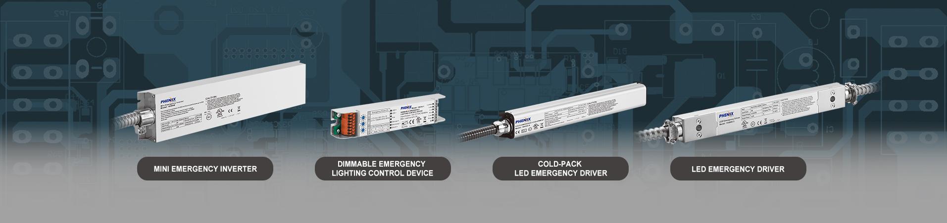
Dimmable Emergency Lighting Control Device 18010-x

Short Description:
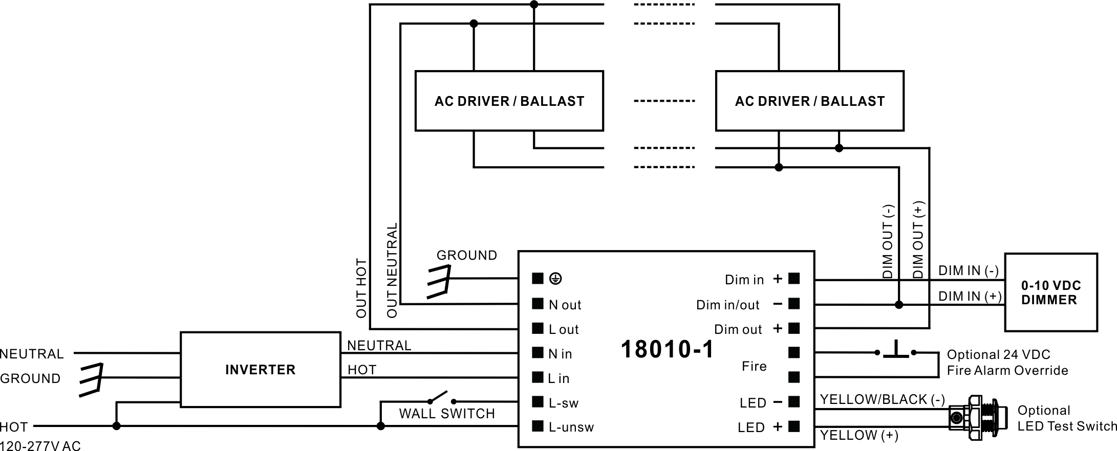
18010-1 Dimmable Emergency Lighting Control Device. Patented APD technology allows generator or inverter supplied emergency lighting to work under auto or preset 0-10V dimming level regardless of wall switch position.


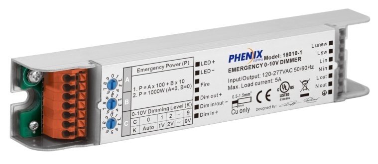
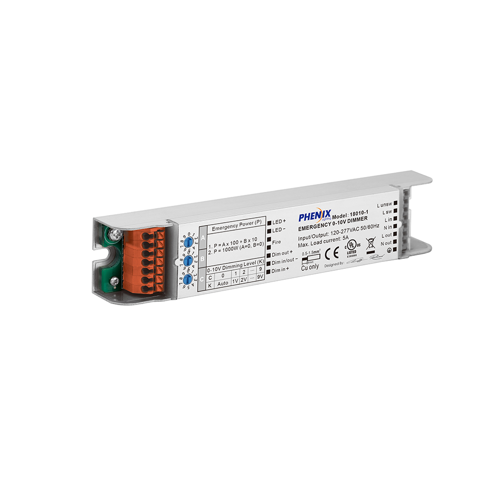
18010-1
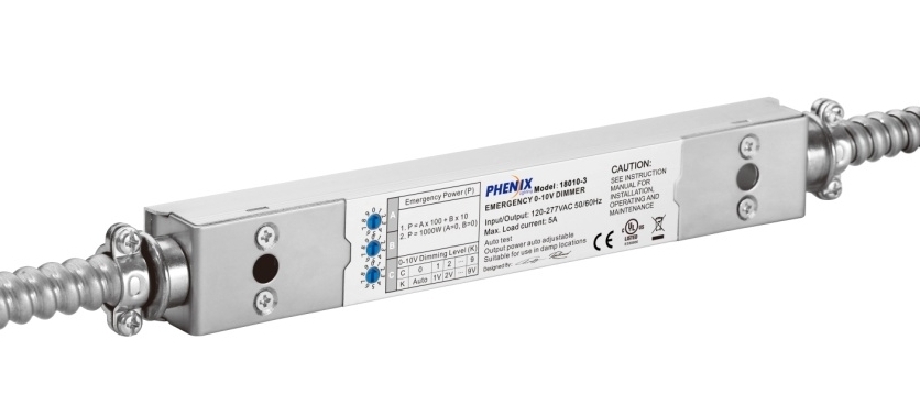
18010-3
1.Patented APD technology allows generator or inverter supplied emergency lighting to work under auto or preset 0-10V dimming level regardless of wall switch position
2.Great energy and cost saving benefits by reduce the power consumption for the emergency lighting
3.Flexible and precise setting to distribute or make the utmost use of the power of a 10-1000W generator or inverter
4.Supports lighting load up to 5A
5.Dimmer, sensor or other lighting controls override capable
6.24VDC fire alarm override capable
7.Various connection options:
|
18010-X |
Description |
|
18010-1 |
Terminal block |
|
18010-3 |
External wires with metal conduits |
8.Slim size
9.Suitable for indoor, dry and damp applications
10.Factory or field installation
| Type | 18010-1 | 18010-3 |
| Rated voltage | 120-277VAC 50/60Hz | |
| Rated current | 20mA | |
| Max. Throughput current | 5A | |
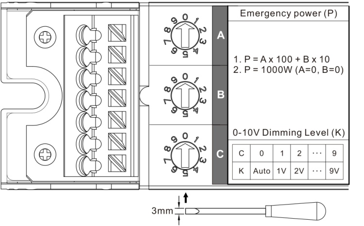
| Input emergency power | 10-600W@120V, 10-1000W@277V (Set by the dipswitch A and B) | |
| Output 0-10V dimming level | Auto dimming or preset of 1V, 2V — 9V (Set by the dipswitch C) | |
| Max. 0-10V Load power | 600W@120V, 1385W@277V | |
| Life time | 5 Years | |
| Operating temp | -20-65°C (4° F- 149° F) | |
| Wire | 16-18AWG/1.0-1.5mm2 | |
| EMC& FCC IC standard | EN 55015, EN 61547, EN 61000-3-2, EN 61000-3-3, FCC part 15, ICES-005 | |
| Safety standard | EN 61347-1, EN 61347-2-7, UL924, CSA C.22.2 No. 141 | |
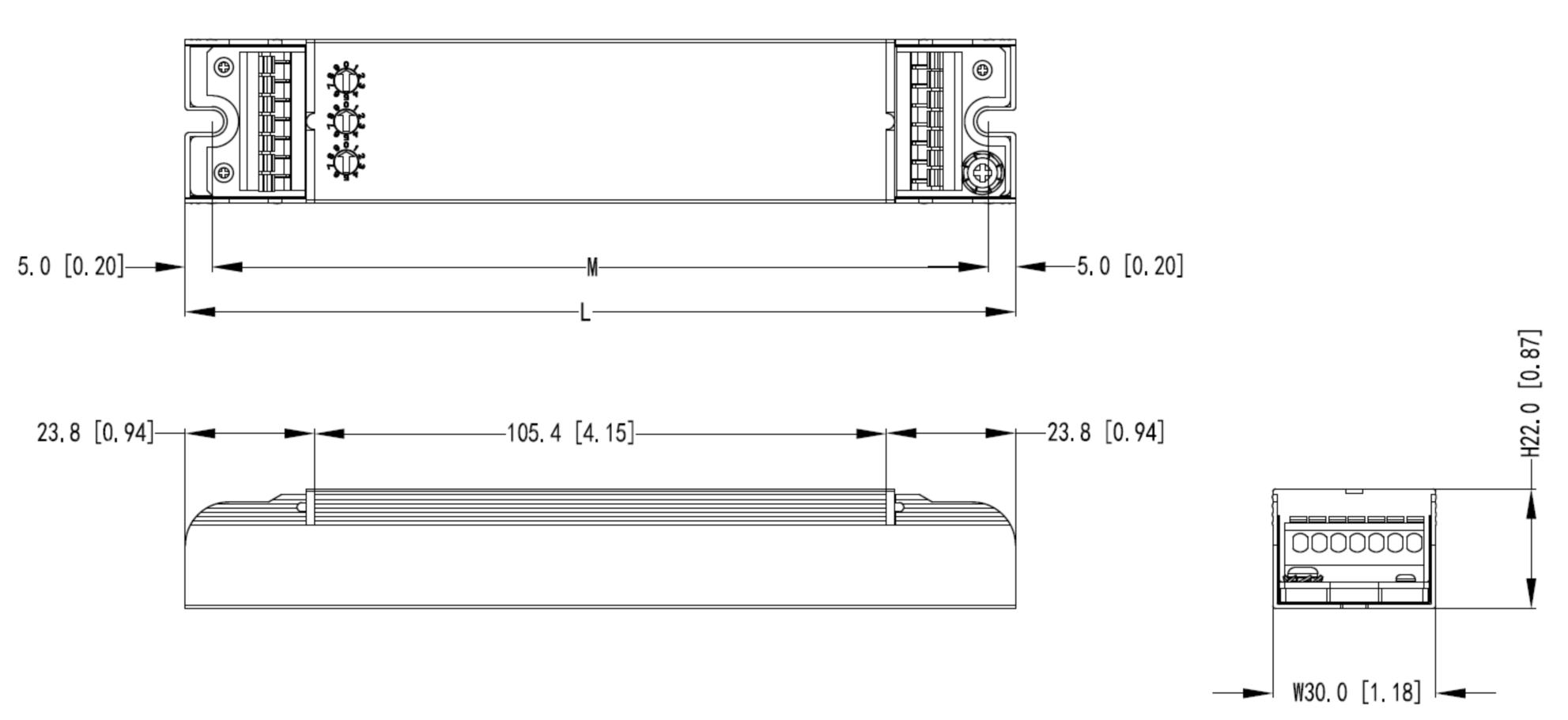
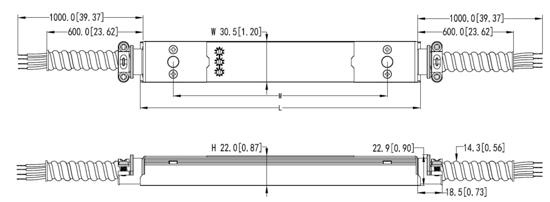
| Meas. mm [inch] | L153 [6.02] x W30 [1.18] x H22 [0.87]Mounting center: 143 [5.63] | L211 [8.31] x W30 [1.18] x H22 [0.87]Mounting center: 162 [6.38] |
18010-1
|
Item No. |
L mm [inch] |
M mm [inch] |
W mm [inch] |
H mm [inch] |
|
18010-1 |
153 [6.02] |
143 [5.63] |
30 [1.18] |
22 [0.87] |
18010-3
|
Item No. |
L mm [inch] |
M mm [inch] |
W mm [inch] |
H mm [inch] |
|
18010-3 |
211 [8.31] |
162 [6.38] |
30 [1.18] |
22 [0.87] |
LED TEST SWITCH
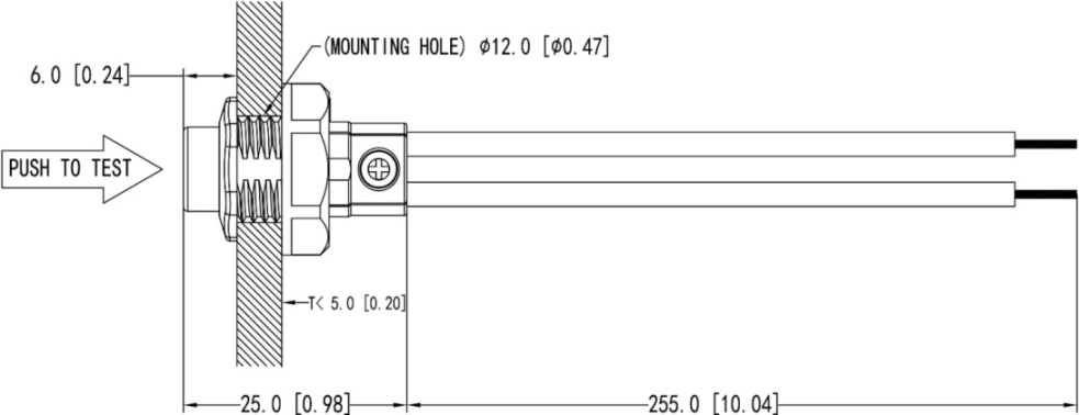
Dimension unit: mm [inch]
EMERGENCY POWER SUPPLY BY SINGLE INVERTER
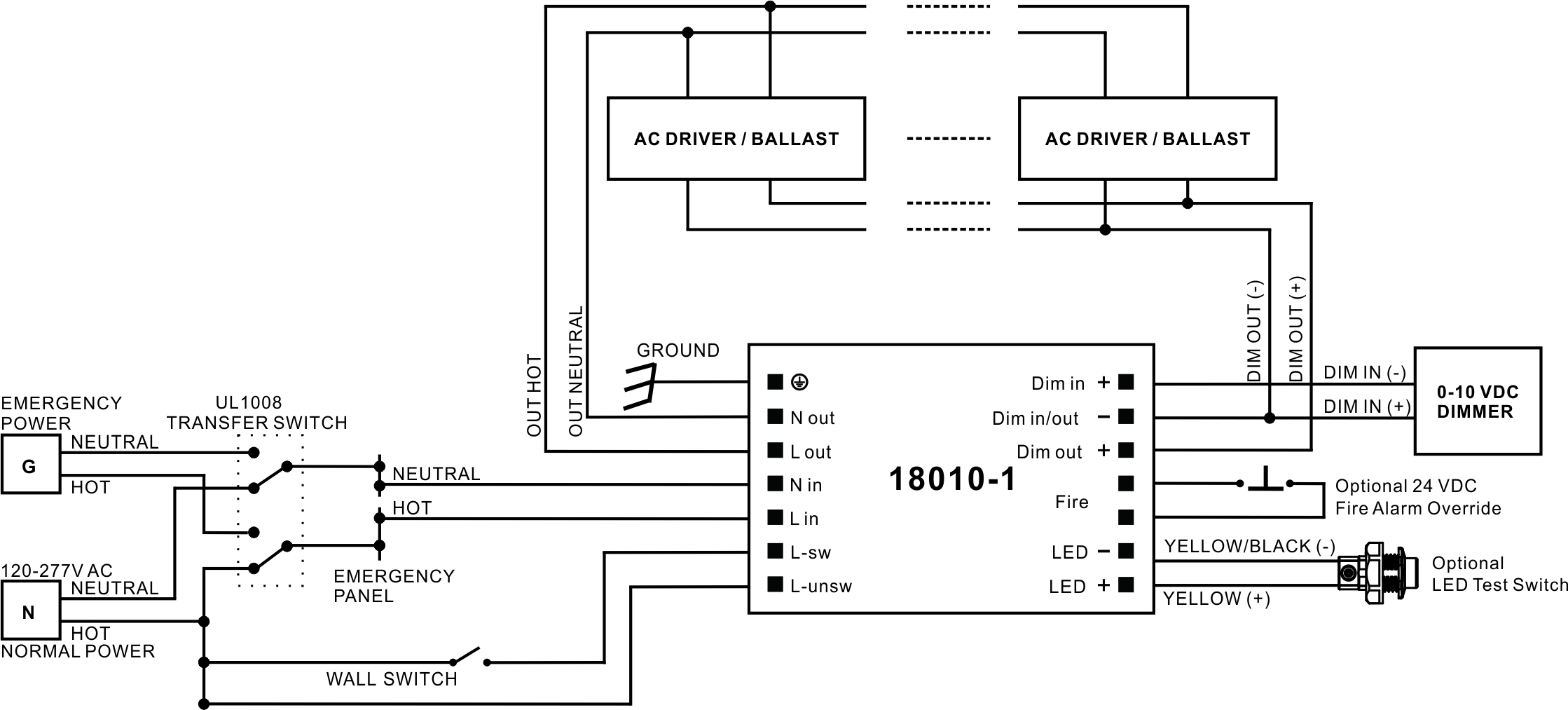
EMERGENCY POWER SUPPLY BY GENERATOR OR CENTRAL INVERTER
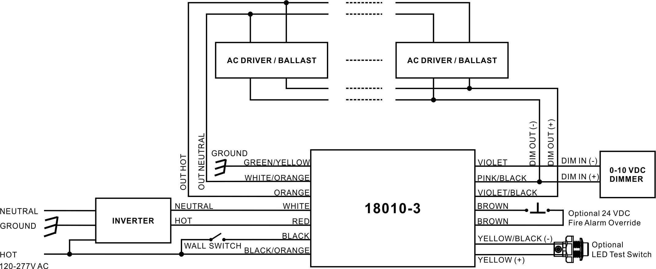
EMERGENCY POWER SUPPLY BY SINGLE INVERTER
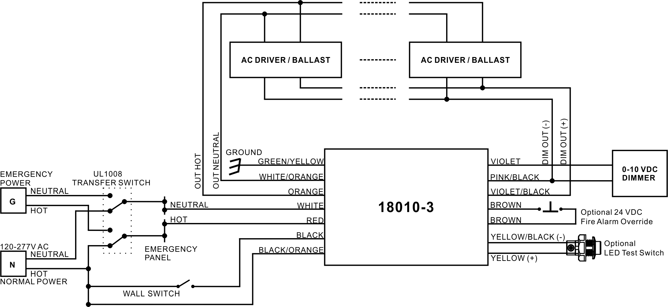
EMERGENCY POWER SUPPLY BY GENERATOR OR CENTRAL INVERTER
OPERATION
The 18010-X dimmable emergency lighting control device can work in conjunction with both an auxiliary generator or a central inverter system and single inverter to power existing fluorescent or LED fixtures for emergency lighting at full or reduced illumination with designed or preset dimming level regardless of the wall switch position or normal dim setting.
TESTING AND MAINTENANCE
1. APD (Auto Preset Dimming) technology (The dipswitch C is set to 0)
a) Initial Auto Test
When the system is connected properly and powered on after a power failure, the 18010-X will perform an initial Auto Test:
Bypassing the wall switch and overriding the dimmer to detect the connected dimmable load’s maximum power – PMax. load, calculating the dimming level – K (which will dim the load in emergency mode) base on the PMax. load and the emergency power(Set by the dipswitch A and B), dimming the load with the dimming level K to simulate emergency mode.
b) Auto adjusting
18010-X is constantly detecting the PMax. load in normal mode, the Initial Auto Test will be restarted automatically when PMax. load increases.
2. Preset dimming (The dipswitch C is set to 1-9)
The dimming level K is preset to 1-9V.
MANUAL TEST (Optional)
– Press the LED test switch (LTS) one time to simulate emergency mode.
– Press the LTS 2 times continuously within 3 seconds to restart the Initial Auto Test.
LED TEST SWITCH (LTS) CONDITIONS
– LTS On: Normal Condition
– LTS Off: Power Failure
– LTS Gradual Change: In Testing Mode