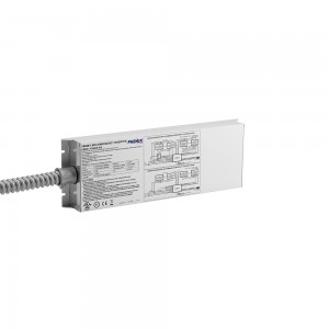
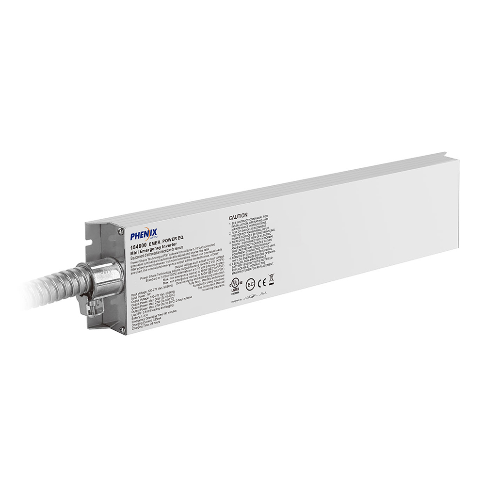
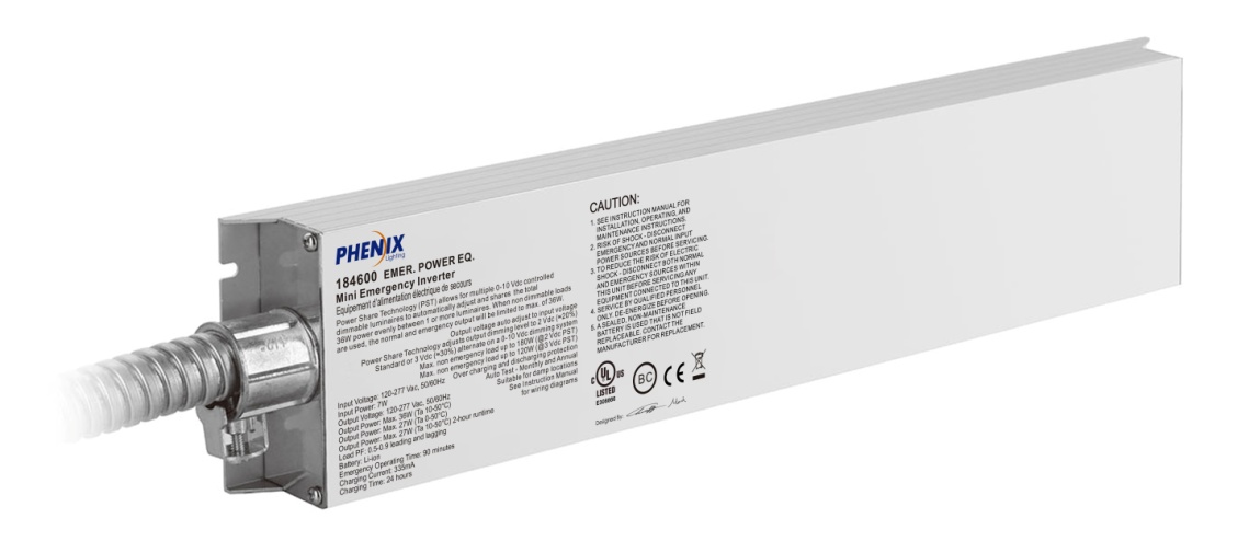
Mini Emergency Inverter 184600/184603 V2

Short Description:
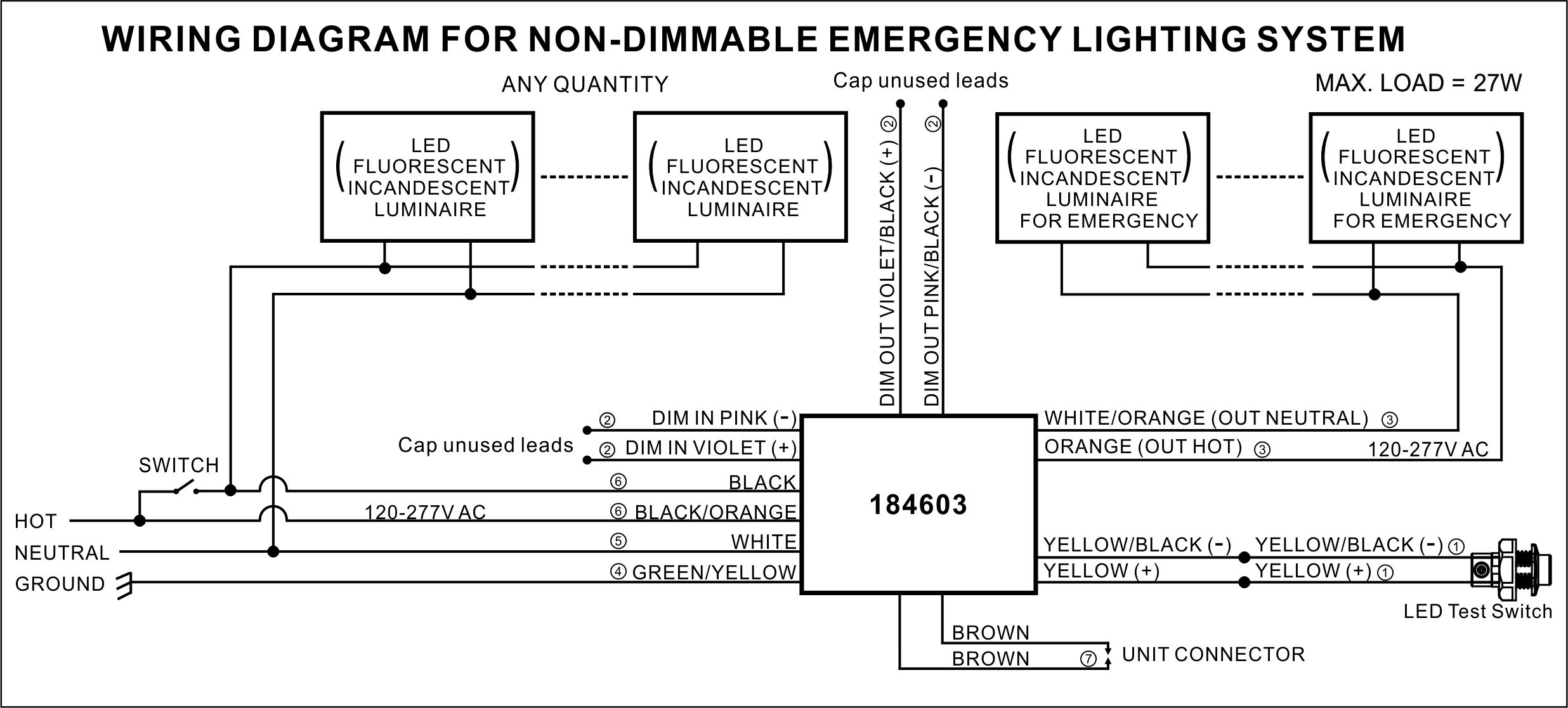
184600 Mini Emergency Inverter 36W, 184603 Mini Emergency Inverter 27W, Pure sinusoidal AC output. The inverter utilizes Power Share Technology (PST) which allows single or multiple 0-10 Vdc controlled luminaires to automatically adjust and share the emergency power.


1. Pure sinusoidal AC output.
2. The inverter utilizes Power Share Technology (PST) which allows single or multiple 0-10 Vdc controlled luminaires to automatically adjust and share the emergency power.
3. Output voltage auto setting according to different input voltages.
4. Auto Test.
5. Extremely slim aluminium housing and light in weight.
6. Suitable for indoor, dry and damp applications.
| Type | 184600 | 184603 |
| Lamp type | LED, fluorescent or incandescent bulbs, tubes and lighting fixtures | |
| Rated voltage | 120-277VAC 50/60Hz | |
| Rated current | 0.1A | |
| Rated power | 7W | |
| Power Factor | 0.5-0.9 leading, 0.5-0.9 lagging | |
| Output voltage | 120-277VAC 50/60Hz | |
| Output power | 36W | 27W |
| Max. power of 0-10V dimming load | 180W | 110W |
| Battery | Li-ion | |
| Charging time | 24 Hours | |
| Discharge time | 90 Minutes | |
| Charging current | 0.34A (Max.) | |
| Life time of module | 5 Years | |
| Charging cycles | >1000 | |
| Operation temperature | 0-50℃ (32°F-122°F) | |
| Efficiency | 80% | |
| Abnormal protection | Over voltage, over current, Inrush current limiting, over temperature, short circuit, open circuit | |
| Wire | 18AWG/0.75mm2 | |
| EMC/FCC/IC standard | EN 55015, EN 61547, EN 61000-3-2, EN 61000-3-3, FCC part 15, ICES-005 | |
| Safety standard | EN 61347-1, EN 61347-2-7, UL924, CSA C.22.2 No. 141 | |
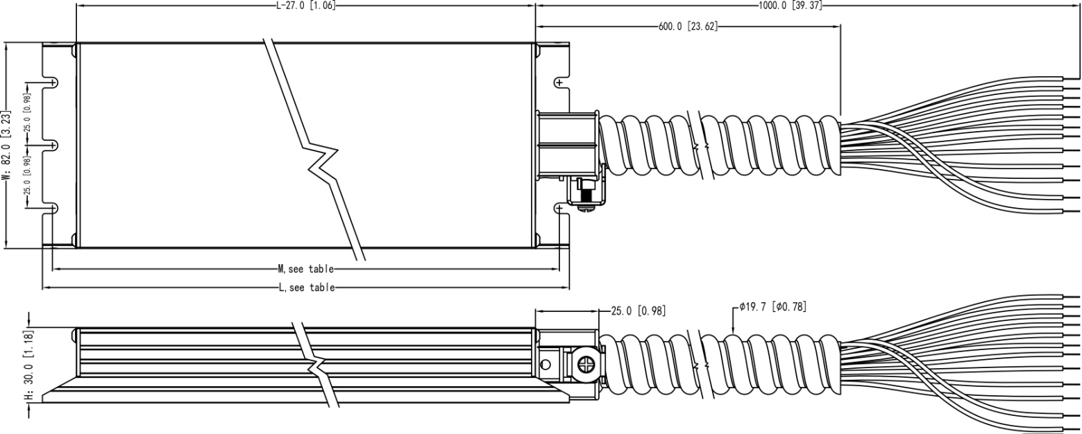
| Meas. mm [inch] | L346 [13.62]xW82 [3.23]xH30 [1.18] Mounting center: 338 [13.31] | |
184600/184603
|
Item No. |
L mm [inch] |
M mm [inch] |
W mm [inch] |
H mm [inch] |
|
184600 |
346 [13.62] |
338 [13.31] |
82 [3.23] |
30 [1.18] |
|
184603 |
346 [13.62] |
338 [13.31] |
82 [3.23] |
30 [1.18] |
Dimension unit: mm [inch]
Tolerance: ±1 [0.04]
184600
184603
OPERATION
184600
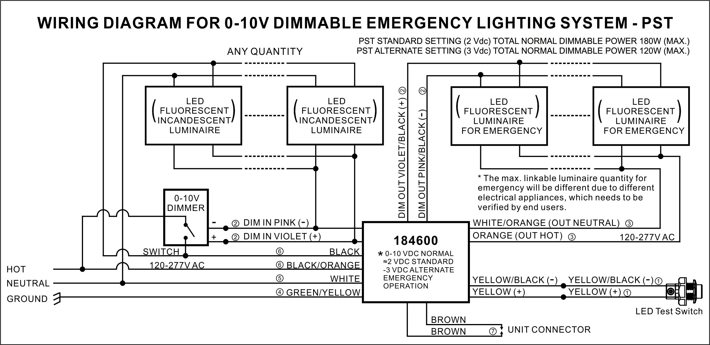
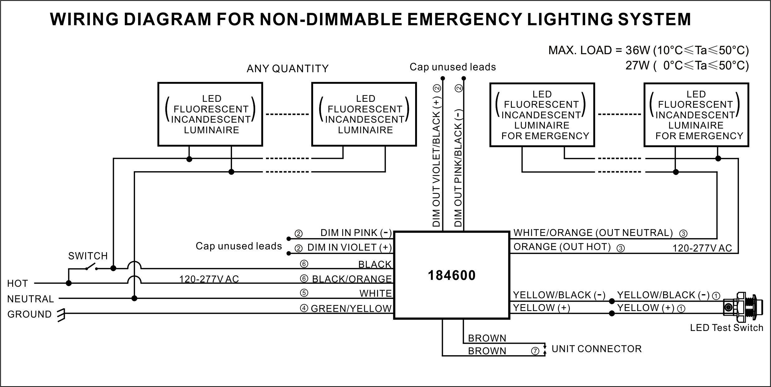
When AC power is applied, the LED test switch is illuminated, indicating that the batteries are being charged. When AC power fails, the 184600 automatically switches to emergency power, operating the lighting load at approximately 20% (Reprogrammed to 30%) of rated luminaire power (max. 180W (PST @ 2 Vdc) or 120W (PST @ 3 Vdc) using Power Share Technology. The 184600 can also be used as a standalone 36W inverter when used with lighting loads less than or equal to 36 watts. During power failure, the LED test switch indicator will be off. When power is restored, the 184600 switches back to normal mode of operation and resumes battery charging. The minimum emergency operating time is 90 minutes. The charging time for a full discharge is 24 hours.
184603
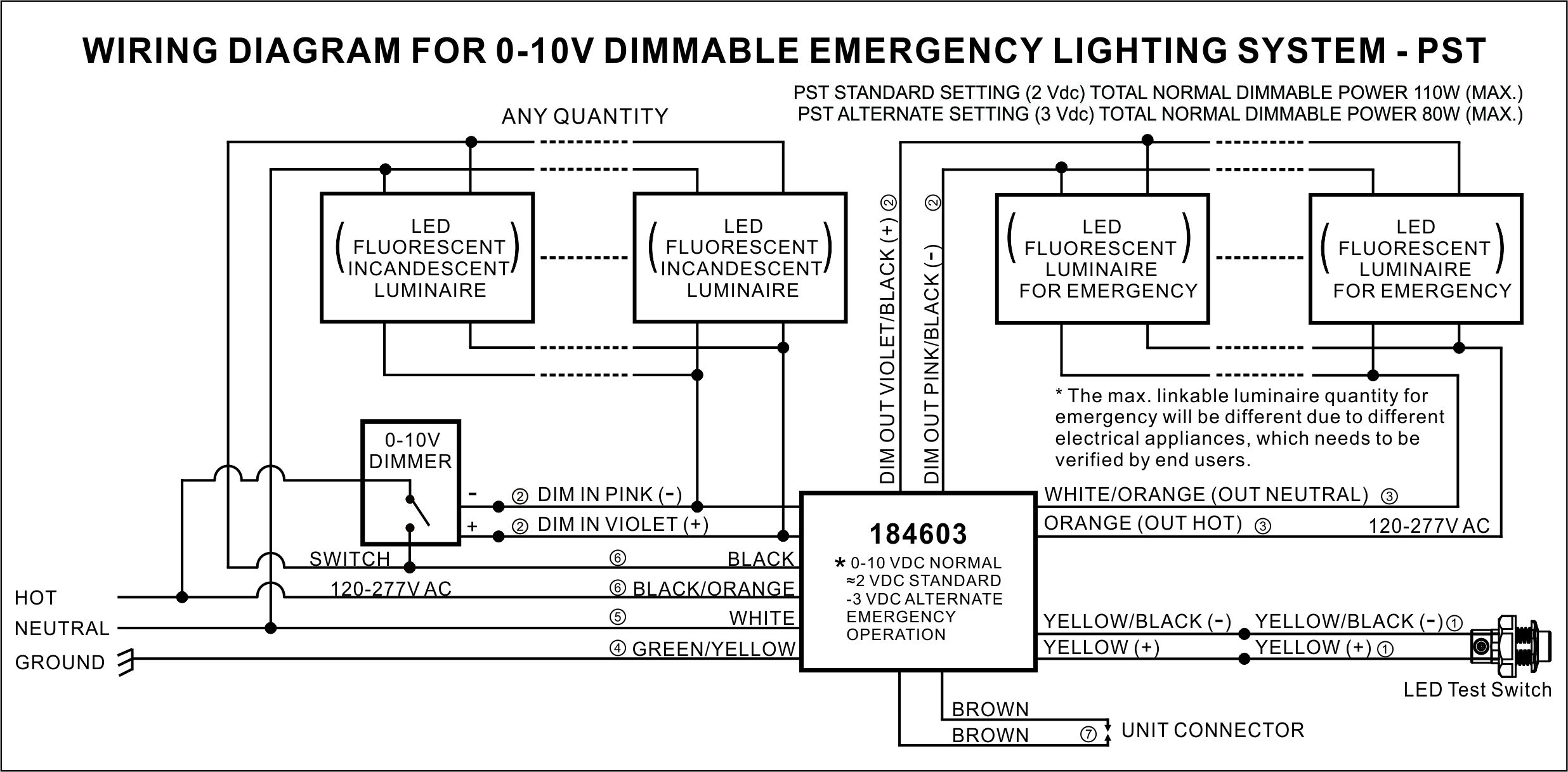
When AC power is applied, the LED test switch is illuminated, indicating that the batteries are being charged. When AC power fails, the 184603 automatically switches to emergency power, operating the lighting load at approximately 20% (Reprogrammed to 30%) of rated luminaire power (max. 110W (PST @ 2 Vdc) or 80W (PST @ 3 Vdc) using Power Share Technology. The 184603 can also be used as a standalone 27W inverter when used with lighting loads less than or equal to 27 watts. During power failure, the LED test switch indicator will be off. When power is restored, the 184603 switches back to normal mode of operation and resumes battery charging. The minimum emergency operating time is 90 minutes. The charging time for a full discharge is 24 hours.
TESTING AND MAINTENANCE
The following Periodic testing is recommended to ensure the system is working correctly.
1. Visually inspect the LED test switch (LTS) monthly. It should be illuminated when AC power is applied.
2. Conduct a 30-second discharge test by switching off the emergency breaker every month. The LTS will be off.
3. Conduct a 90-minute discharge test once per year. The LTS will be off during test.
AUTO TEST
1. Initial Auto Test: When the system is connected properly and powered on, the 184600/184603 will perform an initial Auto Test. If any abnormal conditions exist, the LTS will flash rapidly*. Once the abnormal condition is corrected, the LTS will function correctly.
2. Monthly Auto Test: The 184600/184603 will conduct the first Monthly Auto Test after 24 hours and up to 7 days after initial power on. Then monthly tests will be performed every 30 days, and will test transfer function from normal to emergency, emergency function, charging and discharging conditions. Monthly test time is approximately 30 seconds.
3. Annual Auto Test: It will occur every 52 weeks after the initial 24 hours full charge, and will test proper initial battery voltage, 90-minute emergency operation, and acceptable battery voltage at the end of the full 90-minute test.
*If the Auto Test is interrupted by a power failure, a full 90-minute Auto Test will occur again 24 hours after the power is restored. If the power failure causes the battery to fully discharge, the product will restart the Initial Auto Test, Monthly and Annual Auto Test.
MANUAL TEST
1. Press the LTS 2 times continuously within 3 seconds to force a 30-second monthly test. After the test is complete, the
next (30-day) monthly test will count from this date.
2. Press the LTS 3 times continuously within 3 seconds to force a 90-minute annual test. After the test is completed, the
next (52-week) annual test will count from this date.
3. During any manual test, press and hold the LTS for greater than 3 seconds to terminate a manual test. The Preprogrammed Scheduled Auto Test time will not change.
LED TEST SWITCH (LTS) CONDITIONS
| LTS Conditions |
Default 2 VDC |
Selectable 3 VDC |
| Slow Blinking |
- |
Normal Charging |
| On |
- |
Battery Fully Charged |
| Long ON, Short OFF, Long ON |
Normal Charging and Battery Fully Charged |
- |
| Off |
Power Failure |
|
| Gradual Change |
Testing Mode |
|
| Quick Blinking |
Abnormal Condition – Corrective Action Required |
|
POWER SHARE TECHNOLOGY
184600
The 184600 utilizes Power Share Technology (PST) which allows single or multiple 0-10 Vdc controlled luminaires (up to 180W combined normal luminaire power) to automatically adjust and share up to 36W of emergency AC power. During normal operation, the emergency inverter will pass through normal dimming voltage (0-10 Vdc) on the dim output leads, but then supply a default 2 VDC (or selectable **3 VDC) during emergency operation to achieve approximately 20% (or selectable **30%) of rated luminaire power during an emergency power failure.
** Reduced output mode 3 VDC (~30%) can be selected and easily programmed via the LED test switch (LTS) by depressing the illuminated button for 5 seconds, releasing, then repeating the 5-second button push (i.e. two 5-second extended button pushes within a 13 second timespan). LTS flash conditions confirming 3 VDC mode: Slow Blinking or ON. (Return to the default 2 VDC mode by repeating the extended button press sequence above).
Example (default 2 Vdc setting): Four 45W LED luminaires (180W) would share 9W each of the total 36W emergency power per 184600. 45W x 20% dim = 9W * 4 luminaires = 36W. If the luminaire power is over 45W, then 3 or fewer luminaires can be operated.
Example (3 Vdc setting): Three 40W LED luminaires (120W) will share 12W each of the maximum available 36W emergency power per 184600. 40W x 30% dim = 12W. Similarly, if each luminaire is 30W, then 4 units can 9W each; whereas if the luminaire power is over 40W, then 2 or less luminaires can be operated.
184603
The 184603 utilizes Power Share Technology (PST) which allows single or multiple 0-10 Vdc controlled luminaires (up to 110W combined normal luminaire power) to automatically adjust and share up to 27W of emergency AC power. During normal operation, the emergency inverter will pass through normal dimming voltage (0-10 Vdc) on the dim output leads, but then supply a default 2 VDC (or selectable **3 VDC) during emergency operation to achieve approximately 20% (or selectable **30%) of rated luminaire power during a power failure.
** Reduced output mode 3 VDC (~30%) can be selected and easily programmed via the LED test switch (LTS) by depressing the illuminated button for 5 seconds, releasing, then repeating the 5-second button push (i.e. two 5-second extended button pushes within a 13 second timespan). LTS flash conditions confirming 3 VDC mode: Slow Blinking or ON. (Return to the default 2 VDC mode by repeating the extended button press sequence above).
Example (default 2 Vdc setting): Two 50W LED luminaires (100W) would share 10W each of the total 20W emergency power per 184603. 50W x 20% dim=10W * 2 luminaires = 20W.
Example (3 Vdc setting): Two 40W LED luminaires (80W) will share 12W each. 40W x 30% = 12W, * 2 luminiaire = 24W total for the 184603.
1. To prevent electric shock, switch off the mains power supply until installation is complete and AC input power is supplied to this product.
2. This product requires an un-switched AC power supply of 120-277V, 50/60Hz.
3. Make sure all connections are in accordance with the National or Canadian Electrical code and any local regulations.
4. To reduce the risk of electrical shock, disconnect both normal power, emergency power supplies and unit connector of this product before servicing.
5. For emergency operation of LED, incandescent, fluorescent fixtures and screw-base lamps.
6. Use this product in 0°C minimum, 50°C maximum ambient temperatures (Ta). It can provide minimum 90 minutes illumination under the emergency mode.
7. This product is suitable for use in dry or damp locations. Do not use outdoors. Do not mount it near gas, heaters, air outlets or other hazardous locations.
8. Do not attempt to service the batteries. A sealed, non-maintenance battery is used that is not field replaceable. Contact the manufacturer for information or service.
9. As this product contains batteries, please be sure to store it in an indoor environment of -20°C ~30°C. It must be fully charged and discharged every 6 months from the date of purchase until it is officially put into use, then recharged 30-50% and stored for another 6 months, and so on. If the battery is not used for more than 6 months, it may cause excessive self-discharge of the battery, and the resulting reduction of battery capacity is irreversible. For products with separate battery and emergency module, please disconnect the connection between battery and module for storage. Due to its chemical properties, it is a normal situation for the battery capacity to decline naturally during use. Users should take this into account when choosing products.
10. The use of accessory equipment not recommended by the manufacturer may cause an unsafe condition and void warranty.
11. Do not use this product for other than intended use.
12. Installation and service should be performed by qualified service personnel.
13. This product should be mounted in locations and at heights where it will not readily be subjected to tampering by unauthorized personnel.
14. Ensure product compatibility before final installation. Make sure the polarity is correct when connecting the batteries. Wiring should be strictly in accordance with the wiring diagram, wiring errors will damage the product. A case of safety accident or product failure caused by users’ illegal operation does not belong to the scope of customer complaint acceptance, compensation or product quality assurance.